We deliver across the EU. Pick the language you prefer; you can change it later at the top of the page.
Neu: clightstore.de ist jetzt Teil von clightstore.com.
Gleiche Produkte, gleiche Preise, gleiches Team. Bestellungen aus unserem bisherigen Shop werden wie gewohnt bearbeitet. Kundenkonten und Bestellhistorie des alten Shops sind vorübergehend nicht verfügbar. Bei Fragen erreichen Sie uns unter sales@clightstore.com.
Account
Connecting an LED Light Fitting: Step-by-Step Guide
A standards-compliant step-by-step guide to connecting LED light fittings in commercial environments – from driver selection to IP rating.
14 min readBy Clightstore lighting plannersUpdated 21.10.2026
Connecting an LED light fitting in a commercial environment follows different rules from a DIY installation in a living room: driver sizing, compliance with BS EN 12464-1 and the correct IP rating determine operational safety and sign-off. This guide is aimed at qualified electricians, facility managers and procurement professionals planning and commissioning LED installations in warehouses, workshops, offices or outdoor areas.
In brief
Work on 230 V/400 V installations must be carried out exclusively by competent, qualified electricians (BS 7671, Electricity at Work Regulations 1989).
Before any work: isolate the circuit, verify absence of voltage, and observe all five safety rules.
LED drivers (constant current or constant voltage) must be matched to the fitting – an incorrect driver can damage the LED board or trip the RCD.
The IP rating must suit the installation environment: IP44 for damp locations, IP65/IP66 for industrial and outdoor use, IP69K for high-pressure cleaning.
Illuminance levels to BS EN 12464-1 (office: 500 lx maintained illuminance Em, fine workshop: 750 lx, warehouse: 100–200 lx) must be taken into account during light planning.
Legal basis: Who is permitted to connect LED light fittings?
In the UK, work on fixed electrical installations – that is, connecting light fittings to the mains – must be carried out by a competent person. The relevant legal framework comprises BS 7671 (Requirements for Electrical Installations, IET Wiring Regulations) and the Electricity at Work Regulations 1989.
For electrical contractors this means: only persons with a recognised electrotechnical qualification or demonstrable competence may connect fittings to 230 V or 400 V supplies. The duty holder is obliged to document that work has been carried out correctly and to arrange periodic inspection and testing in accordance with BS 7671.
The five safety rules must be observed before any work begins:
Isolate (switch off the circuit breaker or remove the fuse)
Secure against re-energisation (lock-off or warning notice)
Verify absence of voltage (using a suitable two-pole voltage tester)
Earth and short-circuit (for high-voltage installations)
Cover or barrier adjacent live parts
Step by step: connecting an LED light fitting in a commercial setting
Step 1 – Light planning and standards check
Light planning must be completed before installation begins. What maintained illuminance Em (lx), UGR limit and colour rendering index Ra are required for the application? The table below provides an overview based on BS EN 12464-1:2021.
Application
Maintained illuminance Em (lx)
UGR limit
Minimum Ra
Recommended IP rating
Office – writing, reading, screen work
500
≤ 19
≥ 80
IP41 / IP44
Workshop – rough work
300
≤ 25
≥ 80
IP65
Workshop – fine work / quality inspection
750
≤ 19
≥ 90
IP65
Warehouse / logistics
100–200
≤ 25
≥ 60
IP65
Production hall (general)
300–500
≤ 22
≥ 80
IP65
Sports hall (BS EN 12193)
300–750
≤ 22
≥ 65
IP44 / IP65
Outdoor / car park
20–50
–
≥ 60
IP66 / IP67
For precise light planning in DIALux, we recommend defining the room geometry, surface reflectances and maintenance factor (MF, typically 0.67–0.80) at this stage. Clightstore offers a free DIALux light planning service – please contact us before placing your order.
Step 2 – Select the fitting type and driver
LED light fittings require an electronic driver that converts the mains supply into the operating parameters suited to the LED board. There are two fundamental principles:
Driver type
Output
Typical application
Key characteristic
Constant current (CC)
Fixed current (e.g. 350 mA, 700 mA, 1050 mA)
LED panels, high bays, downlights
Voltage varies; current remains constant – protects the LED from overheating
Constant voltage (CV)
Fixed voltage (12 V DC or 24 V DC)
LED strips, linear lights
Current varies; voltage remains constant – allows simple parallel connection
In commercial installations with multiple fittings on a single circuit, inrush current must be taken into account. Modern LED drivers can momentarily draw many times their rated current at switch-on. With several fittings on one circuit this can trip the circuit breaker even though no fault is present. The solution is to use a Type D circuit breaker or to distribute the fittings across multiple circuits.
All LED panels from Clightstore are supplied with an integrated driver – separate driver sizing is not required. For LED panels with selectable wattage (18 W/25 W), the power can be adjusted directly at the driver, which greatly simplifies planning.
Step 3 – Prepare tools and materials
For a standards-compliant installation, the qualified electrician will need the following tools and materials:
Connectors (WAGO or equivalent) or terminal blocks rated for the conductor cross-section
Cable NYM-J 3×1.5 mm² (for individual fittings up to 16 A) or NYM-J 5×1.5 mm² (for three-phase installations)
Fixings appropriate to the ceiling or wall construction
Junction boxes with the appropriate IP rating
Inspection and test record form for commissioning documentation
Step 4 – Isolate the circuit and verify absence of voltage
Switch off the relevant circuit breaker in the distribution board and secure it against re-energisation. Then use the two-pole voltage tester at the connection point to verify: line (L) to neutral (N) and line to earth (PE) must both read 0 V. Installation work must not begin until absence of voltage has been confirmed.
Step 5 – Identify conductors and make connections
The colour coding required by BS 7671 is as follows:
Brown: Line conductor (L) – live
Blue: Neutral conductor (N)
Green-and-yellow: Protective earth conductor (PE)
Grey: Second line conductor or switch wire (in two-way switching arrangements)
In older installations, non-harmonised colours may be present (e.g. black for N, red for L). In such cases, measurements must be taken before making any connections in order to identify the conductors unambiguously. Never rely on colours that do not conform to the current standard.
Connection sequence: Connect the protective earth conductor (PE) first, then the neutral (N), and finally the line (L). When disconnecting, reverse this order.
Step 6 – Fix the fitting and ensure cable restraint
The fitting must be mechanically secure and must not be supported by the cable. For recessed fittings (LED panels in grid ceilings, LED recessed spotlights), spring clips or mounting frames must be fitted so that the fitting sits flush and no thermal bridges are created. Suspended ceiling voids must be adequately ventilated – heat build-up significantly reduces driver service life.
Step 7 – Commission and test
After making connections: switch on the circuit breaker, verify correct operation, and measure protective conductor resistance and insulation resistance (in accordance with BS 7671 Part 6). Record all measured values in the commissioning certificate. On RCD-protected circuits: carry out the RCD trip test. Leakage currents from multiple LED drivers can accumulate and cause nuisance tripping of the RCD – on large installations, check the leakage current per driver and consider using a time-delayed (Type S) RCD where appropriate.
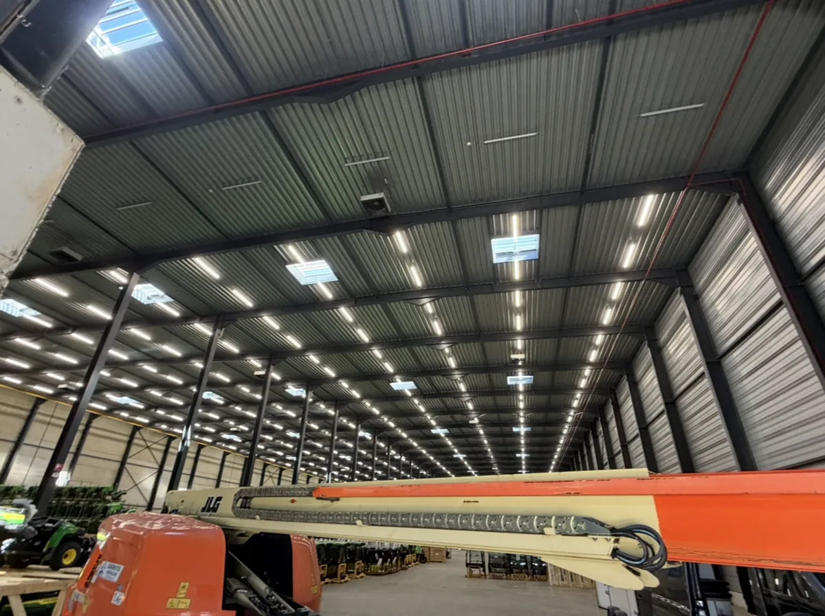
Standards-compliant LED lighting in a logistics warehouse: IP65 high bays above high-bay racking, designed to BS EN 12464-1.
IP ratings: choosing the right protection for every environment
The IP rating (Ingress Protection, standardised in IEC 60529 / BS EN 60529) indicates how well a fitting is protected against dust and moisture. Selecting the wrong IP rating is one of the most common installation errors in commercial settings. A detailed explanation of all IP ratings is available in our guide IP ratings explained: IP20, IP41, IP44, IP54, IP69K.
As a general rule of thumb:
IP41/IP44: Office, consulting room, grid ceiling – no direct water jet
IP65: Warehouse, workshop, dusty production areas – protected against water jets from any direction
IP66: Outdoor areas, facades, multi-storey car parks – protection against powerful water jets
IP67: Temporary immersion to 1 m – outdoor installations with flood risk
For LED tri-proof lights in warehouses and production facilities, IP65 is the recommended minimum standard. In areas with ammonia exposure (e.g. livestock housing, cold stores), specially ammonia-resistant fittings rated IP69K are required.
Recommended LED tri-proof lights for warehouses, workshops and industry – IP65 to IP69K, Tridonic and Osram drivers, up to 5 years' warranty:
Specific considerations for commercial installation types
LED panels in grid ceilings (office, consulting room, school)
LED panels can be recessed (into grid ceilings), surface-mounted (with a surface mounting frame) or suspended. For recessed installation, ensure that the ceiling structure can bear the weight and that heat dissipation is not obstructed by insulation. The driver is generally integrated within the housing or mounted separately in the suspended ceiling void.
For offices with display screen workstations, BS EN 12464-1 specifies a UGR limit of ≤ 19. Our LED panels 120×30 and LED panels 60×60 with UGR<19 meet this requirement straight from the box.
LED panels for office and commercial use – UGR<19, selectable wattage, driver included, 5 years' warranty:
LED high bays and tri-proof lights in industrial buildings
In buildings with ceiling heights above 6 m, LED high bays are used. These are typically suspended on wire ropes or wall brackets and connected via fixed wiring (NYM-J 3×1.5 mm² or 3×2.5 mm²). When daisy-chaining multiple tri-proof lights, the maximum number of fittings that can be linked must be taken from the product data sheet – overloading the supply cable must be avoided.
Daisy-chained LED linear light system in a production hall: series connection of IP65 tri-proof lights saves installation time and cable costs.
LED downlights and recessed spotlights
For LED downlights and LED recessed spotlights, the recess depth is critical. The cut-out opening must match the specified cutout dimension. When installing into insulated ceilings, a fire-rated downlight cover is required unless the fitting is explicitly approved for installation within insulation. The protective earth conductor must remain correctly terminated at the distribution board even for Class II fittings (double-insulated, no PE connection at the fitting).
Outdoor fittings and sports field lighting
Outdoor installations (car parks, facades, sports facilities) are subject to more stringent requirements for cable routing and connection methods. Buried cables must be run in conduit and provided with adequate earthing protection. LED floodlights for sports facilities are designed to BS EN 12193 – the illuminance level depends on the sport and the competition class. Dedicated product ranges are available for football, tennis and padel court applications.
Common installation errors and how to avoid them
The table below shows the most typical errors in commercial LED installations and their consequences:
Error
Consequence
Solution
Incorrect driver (voltage/current mismatch)
LED board fails, warranty void
Cross-check driver data against fitting data sheet
Too many fittings on one circuit
Circuit breaker trips on inrush current
Use Type D circuit breaker or distribute across multiple circuits
Accumulated leakage current trips RCD
Supply interruption with no apparent fault
Check leakage current per driver; use time-delayed RCD (Type S)
Wrong IP rating selected
Moisture damage, fire risk, insurance invalidated
Select IP rating to match environmental conditions
Heat build-up in ceiling void
Driver overheats, service life reduced
Ensure adequate ventilation; mount driver externally if necessary
No cable restraint
Cable fracture, short circuit, fire risk
Fit cable restraint as specified in the fitting installation instructions
No commissioning certificate
Liability exposure, no basis for periodic inspection
Test and document in accordance with BS 7671 Part 6
Checklist for electrical contractors: before and after installation
This checklist serves as a basis for commissioning documentation and may be used as an appendix to a maintenance contract:
☐ Driver type and rating cross-checked against fitting data sheet
☐ Inrush current considered; circuit breaker type verified
☐ Five safety rules observed; absence of voltage documented
☐ Conductor colours correctly identified to BS 7671
☐ Protective earth conductor (PE) connected and resistance measured
☐ Insulation resistance measured (≥ 1 MΩ to BS 7671 Part 6)
☐ RCD tested and reset (functional test)
☐ Cable restraint and mechanical fixing verified
☐ Commissioning certificate completed and signed
☐ Maintenance factor (MF) and next inspection date recorded
Frequently asked questions
What should I do if there is no earth conductor (PE) present?
For Class I fittings (metal enclosure with PE connection), a missing earth conductor is a safety-critical deficiency. The installation must not be energised. A qualified electrician must run an earth conductor or replace the fitting with a Class II device (double-insulated, no PE required). Temporary solutions without a protective earth are not permissible.
Which cable goes where if the fitting terminals are not labelled?
Brown = line conductor (L), Blue = neutral conductor (N), Green-and-yellow = protective earth (PE). Where non-harmonised colours are present (older installations), a qualified electrician must use a two-pole voltage tester to identify the conductors before making any connections. If in doubt, consult the fitting data sheet or contact the manufacturer.
Can LED spotlights be dimmed with a standard wall dimmer?
Not every LED driver is dimmable. Only fittings with an explicitly dimmable driver (TRIAC, 0–10 V, DALI or PWM) can be dimmed. A standard phase-cut dimmer only works with compatible LED drivers – in other cases it may cause flickering, buzzing or driver damage. Compatibility must be verified before installation.
Why does the RCD trip without any apparent fault?
LED drivers generate capacitive leakage currents to earth (PE). With multiple drivers on a single circuit, these currents accumulate. If they exceed the RCD trip current (typically 30 mA), the RCD will trip even though no insulation fault is present. Solution: check the leakage current per driver in the data sheet, distribute fittings across multiple circuits, or use a time-delayed RCD (Type S, 100 mA).
How many LED fittings can be daisy-chained?
The maximum number of fittings that can be linked is stated in the product data sheet and depends on the cable cross-section and total load. As a guide: with 1.5 mm² NYM-J cable and a 16 A protective device, the maximum load per circuit is 3,680 W. The actual number of fittings depends on the wattage of each fitting. The qualified electrician should allow a safety margin and take the permissible voltage drop into account.
Is IP65 always sufficient for outdoor installations?
IP65 provides protection against water jets from any direction but is not suitable for prolonged immersion or high-pressure cleaning. For outdoor areas exposed to heavy rain or vehicle spray, IP66 is recommended. For areas subject to high-pressure cleaning (food industry, livestock buildings), IP69K is required. Environmental conditions must be fully considered when selecting a fitting.
What cable cross-section do I need for LED high bays?
The cable cross-section depends on the total load, cable run length and permissible voltage drop (maximum 3% to BS 7671). For a 200 W high bay at 230 V, the rated current is approximately 0.87 A – 1.5 mm² is adequate in this case. For long cable runs or multiple fittings on a single circuit, the cross-section must be increased accordingly. The qualified electrician must carry out the precise calculation.
What is the maintenance factor (MF) and why does it matter for light planning?
The maintenance factor (MF) accounts for the reduction in luminous flux caused by soiling and ageing over the service life of the installation. A typical value for LED fittings in clean offices is MF = 0.80; in dusty industrial environments it is MF = 0.67. If the MF is not included in the calculation, the installation may fall below the minimum maintained illuminance required by BS EN 12464-1 after a few years. Clightstore applies the MF as standard in its free DIALux light planning service.
Planning a commercial LED installation and need a standards-compliant light planning service?
Clightstore will produce a free DIALux light plan for your project – including an illuminance verification to BS EN 12464-1, UGR calculation and specific product recommendations. EU-wide delivery in 2–5 working days, up to 5 years' warranty.
Necessary cookies keep the shop working. With your permission we also use cookies for statistics and relevant ads. You can change your choice at any time. Privacy policy
Ordering as a business?
Prices include VAT. EU businesses with a valid VAT number pay 0% VAT (reverse charge). Belgian businesses pay 21% and reclaim it.
At checkout, enter your company name in the field “Company”.
The field “VAT number” then appears below it: enter your VAT number (e.g. NL123456789B01).
The VAT is deducted automatically and your invoice shows the reverse-charge note.